Virtual Science Museum
Valves - Page 2 of 2
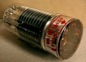 Photomultipliers are very sensitive light detectors. Light is detected by a
photocathode which emits electrons by the photoelectric effect. The tube
contains a series of electrodes called dynodes. The electrons are accelerated
and focused onto the first dynode, where each electron releases a number of
secondary electrons. The secondary electrons are then accelerated to the next
dynode. This tube has 11 dynodes. When the electrons from the final dynode reach
the anode, the photocathode current has been amplified by 1.8x10⁶
times.
Photomultipliers are very sensitive light detectors. Light is detected by a
photocathode which emits electrons by the photoelectric effect. The tube
contains a series of electrodes called dynodes. The electrons are accelerated
and focused onto the first dynode, where each electron releases a number of
secondary electrons. The secondary electrons are then accelerated to the next
dynode. This tube has 11 dynodes. When the electrons from the final dynode reach
the anode, the photocathode current has been amplified by 1.8x10⁶
times.
 This is a Thorn EMI CV2317 photomultiplier tube. It is equivalent to the 6260C, and has an
anode sensitivity of 200A per lumen with a cathode to anode voltage of 1030V.
This is a Thorn EMI CV2317 photomultiplier tube. It is equivalent to the 6260C, and has an
anode sensitivity of 200A per lumen with a cathode to anode voltage of 1030V.
The dynodes in this tube are coated with caesium antimony to give high secondary
emission. Tubes also often use beryllium copper.
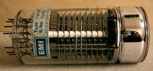
 This is a Sperry 417A klystron. It has an octal base and coaxial take-off ports. The
lever and springs are for tuning.
This is a Sperry 417A klystron. It has an octal base and coaxial take-off ports. The
lever and springs are for tuning.
William Hansen and brothers Russell and Sigurd Varian invented the klystron in 1937.
Klystrons like this one were widely used as the local oscillators in radar receivers
during WW2.
The local oscillator was tuned to exactly the same frequency as the transmitted pulse,
which was usually generated by a magnetron. The local oscillator frequency was mixed
with the received pulse to detect doppler shifted echos from aircraft.
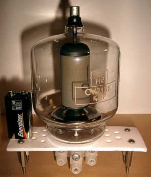 CV2131 tetrode. An equivalent is the 5022.
Max anode voltage: 4kV
Max anode dissipation: 250W
Filament voltage: 5.0V
Filament current: 14.1A
Max screen voltage: 600V
Max screen dissipation: 35W
Max control grid dissipation: 10W
Max DC control grid voltage: -500V
Max DC anode current: 350mA
Mutual conductance: 4.0mA/V
Max anode top cap temperature: 170C
Thanks to Roeland for locating this information.
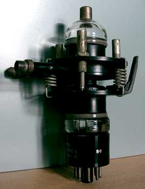
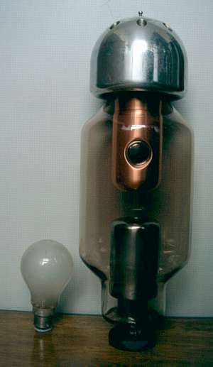 This is a large fixed anode X-ray tube. The standard 60W light bulb is for scale.
X-ray tubes work by accelerating electrons in a field of 40kV or more and then colliding
them with a target. X-rays are produced by interactions with the target atoms. X-ray
tubes are not very efficient and most of the power is dissipated as heat in the anode.
The cathode filament is inside the lower cylinder. The anode is inside the copper
heatsink cylinder above it. The dark circle in the copper cylinder is the x-ray
window. This window is probably made from beryllium to minimize X-ray absorption.
The aluminium dome on the top of the tube is the external anode heatsink. Air would
have been forced through the holes in the heatsink and over the glass envelope to
keep it cool. The heatsink is a smooth dome shape because it is connected to the
anode EHT supply. The smooth surface minimizes corona discharge.
This is a non-functional tube. An X-ray tube of this type must have the pressure
inside it at less than 10-4mBar. The pressure in this tube is around
10-2mBar. This causes a glow discharge between anode and cathode,
preventing the EHT from reaching a workable voltage.
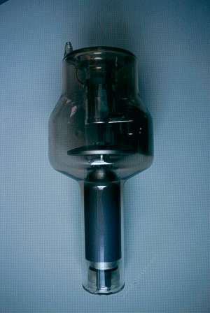 This is a rotating anode medical X-ray tube. It has two filaments so that
the source spot size can be chosen to be large or small. The anode is spun
so that the power is distributed in an annulus rather then on one small spot.
This reduces the cooling difficulties and hence reduces the size of the tube.
This is a rotating anode medical X-ray tube. It has two filaments so that
the source spot size can be chosen to be large or small. The anode is spun
so that the power is distributed in an annulus rather then on one small spot.
This reduces the cooling difficulties and hence reduces the size of the tube.
In this picture, the anode is at the bottom. The rotor of the motor is actually inside
the glass envelope. The motor coils would have fitted over the lower portion of the
tube.
This tube has also failed, but in a different way to the one above. What appears to
have happened is that for some reason, the anode stopped rotating. The result of
this can be seen in the next two pictures.
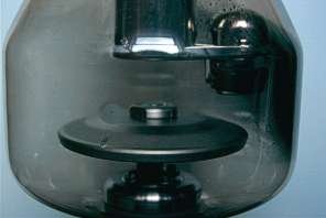 The cathodes and reflectors are in the egg shaped thing to the right of the picture.
The anode disc is in the lower half of the picture. When it stopped rotating, the
power was concentrated on one small area of the circumference, causing it to melt.
The damage to the anode can be seen at the front of the disc, a little to the left.
The anode material evaporated in the vacuum and was deposited on the glass envelope
on the right hand side. This area can be seen in the next picture.
The cathodes and reflectors are in the egg shaped thing to the right of the picture.
The anode disc is in the lower half of the picture. When it stopped rotating, the
power was concentrated on one small area of the circumference, causing it to melt.
The damage to the anode can be seen at the front of the disc, a little to the left.
The anode material evaporated in the vacuum and was deposited on the glass envelope
on the right hand side. This area can be seen in the next picture.
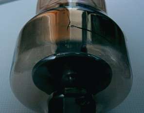 The anode material can be seen deposited on the glass envelope. Radiated heat from
the anode has cracked the glass causing failure of the tube.
The anode material can be seen deposited on the glass envelope. Radiated heat from
the anode has cracked the glass causing failure of the tube.