
| Previous Page | Glass Blowing Menu | Main Menu | Next Page |
|---|
Just over two years on from when I first began glass working I have managed to make a working sealed-off thermionic diode. This is about the most simple thermionic device possible and in its simplest form. It has a directly heated tungsten filament inside a cylindrical anode.
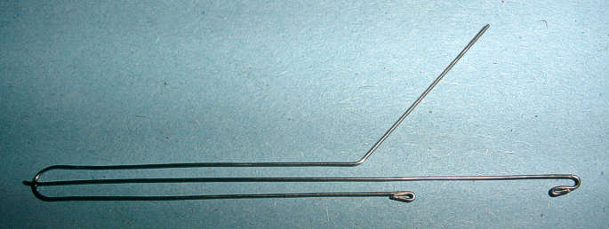
The first step was to make the filament and anode supports. This simply consists of 0.5mm nickel/iron wire shaped as shown above. The middle wire was temporarily spot-welded to the other piece. All welds were made using the home-made spot welder. The top wire is the anode support and the middle and bottom wires are the filament supports.
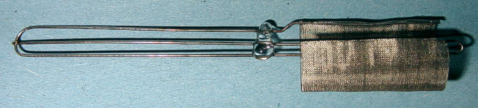
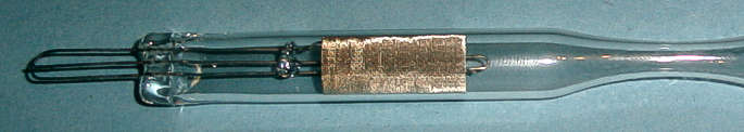
The completed internal structure for the diode is shown above. A glass bead was formed over the three wires to give improved mechanical support for the filament and anode. This was done before the filament and anode were mounted. The anode was made from fine stainless steel mesh. Mesh was used instead of sheet, so that the filament could be inspected for distortion during operation.
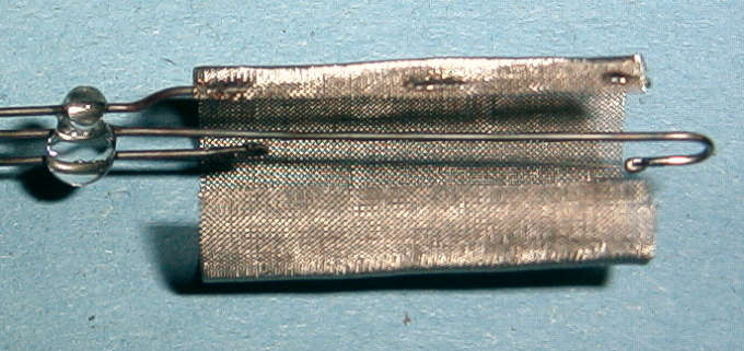
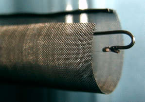 The pictures above and left show the filament crimps. The 0.5mm diameter support
wires were folded over into hooks and the 0.025mm diameter filament wire threaded through.
The hooks were then crimped with a pair of pliers and spot-welded.
The pictures above and left show the filament crimps. The 0.5mm diameter support
wires were folded over into hooks and the 0.025mm diameter filament wire threaded through.
The hooks were then crimped with a pair of pliers and spot-welded.
In the above picture, the spot-welds securing the anode mesh to the anode support
wire can also be seen.
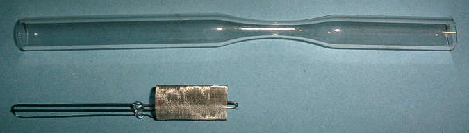
The glass envelope for the diode is simply a length of 12mm diameter soda-lime glass tube drawn down part way along for the pump stem seal. When the internal structure of the diode is inserted into the tube, it is conveniently held in position by the springy anode mesh.
The glass to metal seal is made in the usual way, by heating the end of the tube and then squashing it between two pieces of graphite. In the above picture, the glass to metal seal is complete and the diode is ready to be evacuated.
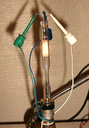 In the picture on the left the diode is on the pump and the pressure is 1x10⁻⁵
torr. It was operated on the pump to de-gas the filament and to compare performance
before and after seal-off.
In the picture on the left the diode is on the pump and the pressure is 1x10⁻⁵
torr. It was operated on the pump to de-gas the filament and to compare performance
before and after seal-off.
The expected performance characteristics for this device were calculated from data given in
Walter H. Kohl, 'Handbook of Materials and Techniques for Vacuum Devices', section 16.
The data was mainly taken from Table 16.5, but with some interpretation of the data based
upon tables and graphs elsewhere in section 16. In particular, π was omitted from the
emission calculation, since the figures agree better with graphs 16.1 and 16.3 without
it. The evaporation rate figure in table 16.5 for 2700K seems to be incorrect. It has been
assumed that it should be 9.95x10⁻⁸. The Power column in table 16.5 has not been
used, but it also seems to have π included in error.
The results of these calculations are presented in the tables below. Note that these are
predicted performance figures, not measurements taken from the diode.
| Wire Diameter D (cm) | 0.0025 |
| Wire Length L (cm) | 1.8 |
| (W) Density (g/cm3) | 19.3 |
| Temp | A/(D1.5) | (1000 V D0.5)/L | Current | Voltage | Power |
|---|---|---|---|---|---|
| (K) | * | * | (A) | (V) | (W) |
| 2400 | 1422 | 127.5 | 0.178 | 4.59 | 0.816 |
| 2500 | 1526 | 143.6 | 0.191 | 5.17 | 0.986 |
| 2600 | 1632 | 161.1 | 0.204 | 5.80 | 1.183 |
| 2700 | 1741 | 179.7 | 0.218 | 6.47 | 1.408 |
| 2800 | 1849 | 199.5 | 0.231 | 7.18 | 1.660 |
| 2900 | 1961 | 220.6 | 0.245 | 7.94 | 1.947 |
| Evaporation | Initial | Time to | |||
|---|---|---|---|---|---|
| Temp | πM / (L D) | M / (L D) | Rate | Mass | 10% Loss |
| (K) | * | (g/sec) | (g) | (hours) | |
| 2400 | 1.37x10⁻⁹ | 4.36x10⁻¹⁰ | 1.96x10⁻¹² | 1.71x10⁻⁴ | 2414 |
| 2500 | 6.36x10⁻⁹ | 2.02x10⁻⁹ | 9.11x10⁻¹² | 1.71x10⁻⁴ | 520 |
| 2600 | 2.76x10⁻⁸ | 8.79x10⁻⁹ | 3.95x10⁻¹¹ | 1.71x10⁻⁴ | 120 |
| 2700 | 9.95x10⁻⁸ | 3.17x10⁻⁸ | 1.43x10⁻¹⁰ | 1.71x10⁻⁴ | 33 |
| 2800 | 3.51x10⁻⁷ | 1.12x10⁻⁷ | 5.03x10⁻¹⁰ | 1.71x10⁻⁴ | 9 |
| 2900 | 1.08x10⁻⁶ | 3.44x10⁻⁷ | 1.55x10⁻⁹ | 1.71x10⁻⁴ | 3 |
| Temp | I / (L D) | I |
|---|---|---|
| (K) | * | (mA) |
| 2400 | 0.364 | 1.6 |
| 2500 | 0.935 | 4.2 |
| 2600 | 2.25 | 10.1 |
| 2700 | 5.12 | 23.0 |
| 2800 | 11.11 | 50.0 |
| 2900 | 22.95 | 103.3 |
* Jones & Langmuir
![]() The above calculations can be downloaded as an Excel spreadsheet. Right click on the icon and choose 'Save Target As...'.
The spreadsheet enables the predicted characteristics to be recalculated for different filament
diameters and lengths.
The above calculations can be downloaded as an Excel spreadsheet. Right click on the icon and choose 'Save Target As...'.
The spreadsheet enables the predicted characteristics to be recalculated for different filament
diameters and lengths.
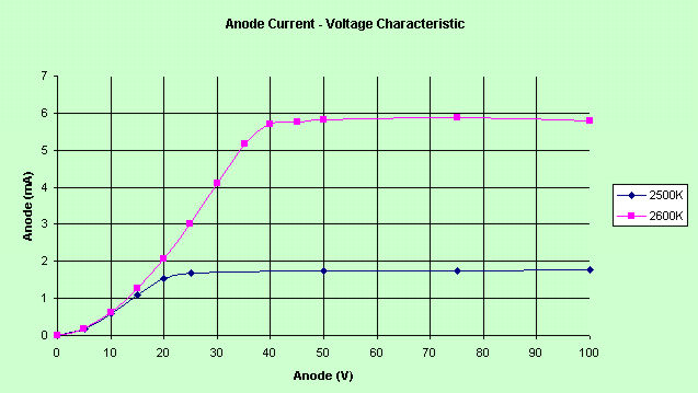
The graph above shows the measured characteristic curve of the diode for two different filament temperatures. The filament currents for predicted temperatures of 2500K and 2600K were 191mA and 204mA respectively.
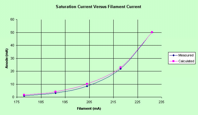
The graph above (blue curve) shows the saturated emission current of the diode after the filament was initially run at 245mA for a short while to de-gas it. This turns out to be a very important step. It increases the emission current at lower temperatures and must be done before the device is sealed-off as a large quantity of gas is driven out. This is evident from a significant rise in pressure. The measured performance can be compared with that predicted from by the tables (purple curve)
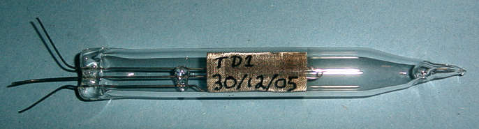
The diode was then sealed-off and detached from the pump (TD1 above). It was re-tested 30 minutes after seal-off.
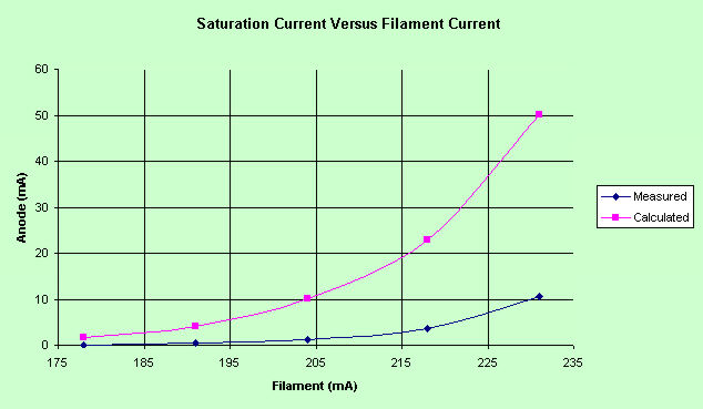
After seal-off, the emission current was seriously down as can be seen in the above graph. The most likely reason for this is leakage through small cracks in the pump stem seal or through the glass to metal seals.
I then destroyed it completely by operating it at a filament current of 245mA. The diode suddenly went so gassy that a pale blue glow appeared inside. This catastrophic failure was probably due to gas evolved from the filament when its temperature was raised to the maximum it had been de-gassed at.
I decided to make a new device identical to the one above, but with the pump seal necked down to 3mm to minimize the risk of cracking and Dumet wire for the glass to metal seals. The Dumet wire was recovered from 240V 60W Mazda filament lamps. This is described on the next page.
| Previous Page | Glass Blowing Menu | Main Menu | Next Page |
|---|