
Evaporation of Metals in High Vacuum
If a metal is heated to melting point in air, not much
happens because it is being heavily bombarded with air molecules. If the same
metal is melted in a high vacuum, something rather interesting happens; evaporation
occurs. The vapour travels until it encounters a cold surface, where it condenses.
For this to happen effectively, the pressure has to be in the region of free
molecular flow. This is when the molecules in the residual gas are so few that
although they strike the walls of the vacuum chamber, they rarely collide with
each other. This occurs at pressures below about 10-7 bar. This process can
be used to produce thin metal films, optical filters, mirrors and beam splitters.
Evaporation using boats
The source metal can be evaporated using a thin tray
made from a high melting point metal, such as molybdenum which has a melting
point of 2622C. The molybdenum tray is known as a boat. A high current
is passed through the boat. The resistance of the boat causes it to heat
up. When the melting point of the metal is reached, evaporation occurs.
This method is simple, but it does have its drawbacks.
Aluminium for example, is quite inert in air because
its surface oxidizes almost instantly. When it is molten in a vacuum it
is highly reactive and alloys with molybdenum. Very low vapor pressure
elements such as molybdenum, tungsten and carbon can not be evaporated
using this method because the boat would melt before the source.
Other ohmic heating methods include the use of
tungsten baskets and filaments.Tungsten has a melting point of 3382C.
This allows it to be used for higher melting point materials.
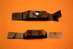 These are molybdenum boats. They are clamped in to support posts at either end.
The support posts deliver the current. The source material to be evaporated
is placed in the bowl.
These are molybdenum boats. They are clamped in to support posts at either end.
The support posts deliver the current. The source material to be evaporated
is placed in the bowl.
The top boat is a Nanotech type MB4, designed to
operate at 55 amps. The bottom boat is a Nanotech type MB1, designed to
operate at 25 amps.
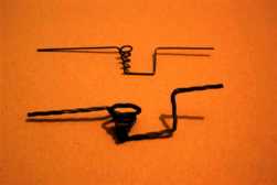 These are tungsten baskets. The material to be
evaporated is placed in the basket. Current is passed through the coil
to heat it. The source material melts and sticks to the basket.
These are tungsten baskets. The material to be
evaporated is placed in the basket. Current is passed through the coil
to heat it. The source material melts and sticks to the basket.
The top basket is a Nanotech type WB3, designed to operate at 20 amps
the lower one is a WB1 designed for 35 amps.
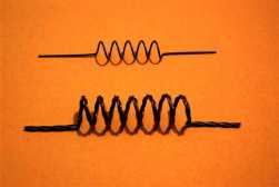 These are tungsten filaments.
The top filament is a Nanotech type WF3, designed to operate at 20 amps.
The bottom filament is a Nanotech type WF2 filament designed to operate at 40 amps.
Source material in wire form is hung over the coils and then melted on.
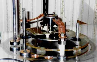
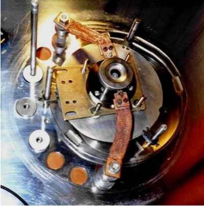
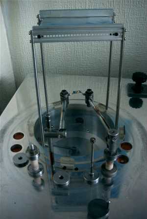 The photo on the left shows the base plate of a vacuum rig. The large
opening in the middle is the entrance to the vacuum pump. A glass bell
jar (removed in the picture) fits over the top. Once evacuated, it is
held down firmly by atmospheric pressure.
The photo on the left shows the base plate of a vacuum rig. The large
opening in the middle is the entrance to the vacuum pump. A glass bell
jar (removed in the picture) fits over the top. Once evacuated, it is
held down firmly by atmospheric pressure.
An MB4 boat is clamped to aluminium supports and loaded with a small
piece of gold. The item to be coated (a sheet of aluminium foil) is held
on the frame at the top.
The holes in the base plate are for electrical feed throughs. Two
ceramic insulated feed-throughs can be seen towards the front of the
base plate.
A variable high current supply is connected to the right hand feed-through
underneath the base plate.
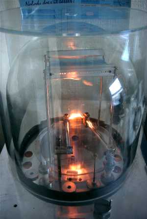 In the picture on the left, the bell jar is in place and has been evacuated
to 1x10⁻⁴mBar.
In the picture on the left, the bell jar is in place and has been evacuated
to 1x10⁻⁴mBar.
There is also a perspex cylindrical cover over the
bell jar which provides operator protection in the event of implosion.
Current is flowing through the boat, heating it white hot. The gold has
melted but has not yet started to evaporate.
The substrate holder supporting the aluminium foil to be coated was home
made from bits of equipment subrack. The legs were made from drive shafts
scavenged from old laser printers. It is fitted with subrack card runners
so that it can hold a sheet of glass. Glass can be coated to make mirrors
and beam splitters.
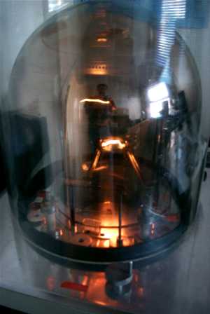 The gold is now evaporating. Atoms go in all directions and coat the bell
jar as well as the intended substrate. It looks bad, but it is actually quite
easy to clean off using acetone.
The gold is now evaporating. Atoms go in all directions and coat the bell
jar as well as the intended substrate. It looks bad, but it is actually quite
easy to clean off using acetone.
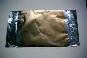 This is the finished item. The central part of the foil is evenly coated
with a thin layer of gold.
This is the finished item. The central part of the foil is evenly coated
with a thin layer of gold.
I used this gold coated foil for one of the experiments on the
X-Rays page.
Evaporation by electron bombardment
This method works by bombarding the source with
a powerful electron beam. Free electrons are created by thermionic emission
and are accelerated towards the source material by an applied electric
field. The electrons give up most of their energy to the metal which causes
it to heat up.
Because electron bombardment heats the source directly,
almost the entire periodic table can be evaporated.
 This is the electron gun mounted on top of the vacuum rig. It is in the
black cylinder at the top of the picture.
This is the electron gun mounted on top of the vacuum rig. It is in the
black cylinder at the top of the picture.
In operation it is covered by a glass bell jar which is evacuated by
the vacuum system. The white pillar in the foreground is one of the high
voltage insulators which bring the HT and filament current into the vacuum
chamber.
 In this picture, the grey source castle can be seen through the top of the
gun.
In this picture, the grey source castle can be seen through the top of the
gun.
The spot in the center of the castle is a small quantity of source
material to be evaporated.
The tungsten heater wires (which are not visible in the picture)
pass above the castle. In operation they are at negative HT potential
and bombard the source with electrons.
I obtained this vacuum rig as surplus equipment. It was made by Nanotech
Thin Films Limited. When I obtained it there was an evaporation gun but no power
supply. I decided to try to build my own. When I found out how much power
was required, I realized that obtaining a suitable transformer was likely
to be a problem. It turns out that the electron gun requires about 3000V
at 0.3A (900W) to evaporate most metals. After pondering this problem for
some time, I suddenly had a brain wave. I needed a scrap microwave oven.
Warning: The voltages inside a microwave oven are lethal. There is also
a pump capacitor which could remain charged even with the oven unplugged.
A microwave oven transformer has a mains powered primary and a secondary
which produces around 2300Vrms at 400mArms. Furthermore, the microwave oven
power supply uses a diode pump circuit which produces 2 times the
transformers peak voltage unloaded.
I got hold of a domestic Saisho oven and took some measurements:
Transformer primary voltage 240Vrms
Transformer primary current 3.8Arms
Filament current 8.5Arms
Filament voltage 3.3Vrms
Secondary HT voltage 2300Vrms
Magnetron HT dc voltage -1.7kV
DC voltage with magnetron disconnected -3.2kV
The power supply was then removed from the oven for a trial. The heater
and HT supplies needed to be independently variable, so the magnetron heater
winding could not be used for the gun filament. Because the gun filament is
at HT potential, the winding which provides the heater current needs to be
well insulated. I used a small torroidal transformer and wrapped it with
PTFE tape. I then wound the heater winding over the top of the tape.
It was not practical to measure the heater current directly with the HT
on, using the equipment available at the time. I therefore made measurements of
heater transformer primary current against secondary current with the HT off.
These values were used to calculate the turns ratio of the transformer.
Knowing the turns ratio enabled the heater current to be estimated during
the trial.
The transformer current formula is i1N1 = i2
N2, where i1 and i2 are the primary and secondary
currents respectively and N1 and N2 are the
number of turns on the primary and secondary respectively. It was found
that a primary current of 221mA produced 9.25A in the secondary. This
indicates a turns ratio of 42:1.
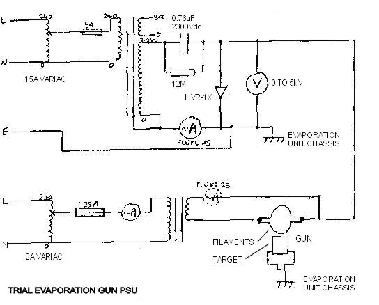
The circuit (shown above) was dangerously lashed together on the work bench
for an initial test. I was actually very careful not to touch anything because
the voltages are lethal.
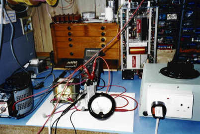 The cylinder on the left and the cream coloured box on the right are the variacs
(variable auto transformers). The transformer on the white plastic sheet is the
one that was removed from the microwave oven. The silver thing immediately to the
right of that is the 0.76μF pump capacitor.
The cylinder on the left and the cream coloured box on the right are the variacs
(variable auto transformers). The transformer on the white plastic sheet is the
one that was removed from the microwave oven. The silver thing immediately to the
right of that is the 0.76μF pump capacitor.
The results of the test are summarized in the following table.
Evaporation Test Results.
| HT Primary
| HT Secondary
| HT at cathode
| Heater primary
|
|
| (Vrms)
| (mArms)
| (kVdc)
| (mArms)
| Notes
|
| 120
| 0.0
| -2.5
| 72.3
| Heater dull orange
|
| 120
| 0.0
| -2.5
| 94.8
| Heater current increased.
|
| 120
| 28.2
| -2.4
| 189.6
| Anode current saturated
|
| 120
| 48.0
| -2.4
| 200
| Anode current slowly falling.
|
| 190
| 48.9
| -3.5
| 199.0
| Material still solid.
|
| 190
| 100.2
| -3.4
| 208
| Rapid evaporation.
|
At low heater current no current flowed in the HT circuit because the heater
temperature was not high enough for the electrons to overcome the work function
of the tungsten. See table rows 1 and 2.
 With the heater transformer primary current at 190mA (heater current 42 x 0.19
= 8A, HT current began to flow. See table row 3.
With the heater transformer primary current at 190mA (heater current 42 x 0.19
= 8A, HT current began to flow. See table row 3.
As the HT power was increased, the chamber pressure began to rise slightly due
to out-gassing.
When the HT power was increased to around 340W the source material melted and
began to evaporate. See table row 6.
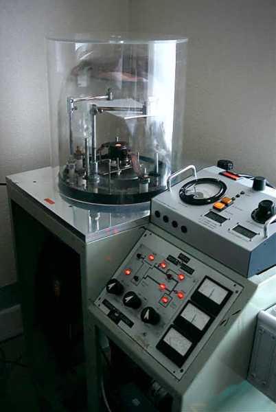
As the trial was very successful, the power supply was built into a control panel
with meters (The box on the top right of the machine). The microwave oven transformer
and pump capacitor were housed in a box on the end of the machine. Above, the rig is
being used to coat a sheet of paper with copper.
Pump-down took quite some time because of the moisture content of the paper.
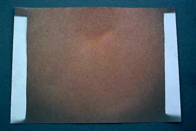 This is the paper after it had been coated. It has a resistance of 0.5
Ω / cm.
This is the paper after it had been coated. It has a resistance of 0.5
Ω / cm.
In 2006 I managed to make a working thin-film
photo-electric cell
using the vacuum coater.